](/media/headers/kart.jpg) Image credit: pixabay
Image credit: pixabay
Kart Timing Mk1
This page documents a hobbyist kart timing system that I developed last year (2012). It was used for a week at a summer camp for youths and it worked quite well. However there are a number of improvements that need to be made which I am progressing this year.
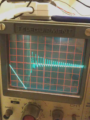
I owe much of the success of this project to others, firstly a very kind gentleman named Tony. Without him I would never have got this working as quickly as I did. He generously lent me my first scope (a Telequipment cathode ray oscilloscope!) and encouraged me to make a success of the entire project. Thanks also to Dan & Rich for technical ideas and numerous others for entertainment along the way.
Why I did it
I help at a summer camp for 13-18 year olds and funds that can be saved are spent wisely elsewhere, we simply don’t have the money for lots of fancy timing equipment. However this was also a fun challenge and I learnt a lot in the process.
Professional equipment is more accurate but is also expensive, especially for use just one week a year.
During the week we also run a number of different types of races. Many are team events where individuals change between vehicles, which popular software doesn’t make easy.

The approach
This wasn’t the first attempt I had made at timing. Everything from IR to GPS was on the cards and I made varied progress with a number of solutions. Professional systems run on magnetic induction: a loop in the track receives a signal from a small transponder placed on each kart and this is decoded by a box which is (usually) connected to a PC.
Fortunately I discovered that some work had been done before, a system had been developed which previously functioned at the track we use. Unfortunately the transponders had fallen into disrepair and there was no receiver for it, the original design also never included PC connectivity.
I was given an example transponder and a test fixture for the receiver which lit some LEDs to indicate which transponder had been detected. My goal was to produce at least six transponders (one per kart) and a USB connected decoder which would work with popular PC software.
Design (transponders)
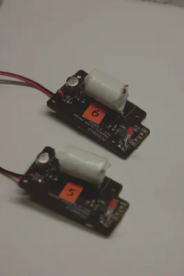
A small transponder sits on each kart which sends a pulse periodically. In the system I was cloning the transponders used 9v batteries and a custom wound inductive coil.
Unlike proper timing systems, which use a modulated carrier, the transponder I was working with relied on the spike created as the electromagnetic field round the inductor collapsed. This creates a very messy spectrum.
Individual karts are identified by the distance between pulses. A loop under the track receives these pulses, amplifies them and sends this back to the PC down a current loop. During testing I found that pulse gaps between 1mS and 1.5mS worked well and, if required, this could be extended to a maximum gap of 2mS.
In order to get reliable identification the gap interval needed to be at least 0.1mS (100µS). This is partly due to the ringing that occurs when power to the coil is cut, as the magnetic field around the ferrite rod collapses.
This allows a maximum of 6 karts (1.0mS, 1.1mS .. 1.5mS) or 10 at a push. At the best case this means that the first kart (with a 1mS gap) is sending 1000 pulses a second but the sixth kart (with a 1.5mS gap) is only sending 666. This is an obvious flaw, but did not stop the system working.
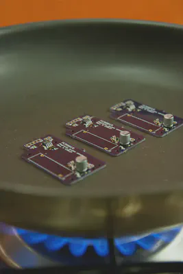
Progress (transponders)
Design (decoder)
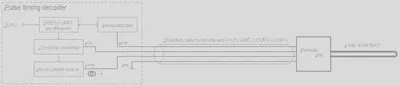
A block diagram of the decoder is shown below. The decoder is connected to a remote unit which contains an opamp (as a comparator), a monostable (to latch the signal for a short time) and a current loop transmitter.
The decoder needed to:
- Supply +12v for a remote unit, buried next to the track
- Provide a 20mA current source for a current loop, used for communication with the remote unit
- Decode the pulses coming back from the remote unit
Trial and error led to the breadboard below, which is almost a fully functional decoder. The current loop is terminated with a 200Ω resistor and one of the PIC comparators is used to watch for changes which correspond with pulses.
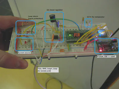
To reduce the effects of spurious detections the microcontroller waits until it has seen the same ID number three times in quick succession before it will register a detection. These spurious events are caused by noise or radio interference. This area is one that needs to be improved first in the new revision.
Most PC software expects to read from a serial port, so using an FTDI FT230XS was a simple solution. These are very well supported across all operating systems and can negotiate power appropriately for the boost regulator, including a “soft start” to help manage the inrush current.
Despite many websites claiming that the USB standard does not enforce the maximum power limits I found that the connection would occasionally reset if the boost regulator was allowed to start up before USB negotiation had completed. There is also a very important maximum capacitance limit which should be adhered to for correct operation.
Completed circuit (decoder)
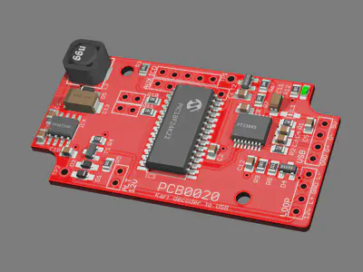
Somewhere along the way I decided to play with Eagle3D. Below is a rendering I did of the decoder board at a fairly late stage. The board had been designed to fit in a plastic case made by Hammond and it was good to visualise how well screws would clear the components.
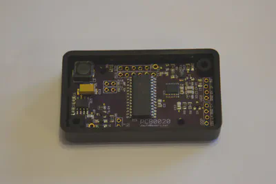
The completed board is shown below. One lesson of many was to use a proper connectors, especially for USB. Leaving wire headers is not a sensible option and I ended up fixing them with hot melt glue a number of times!
After many hours of debugging I also learned the valuable lesson that polarity for tantalum SMD capacitors is marked “backwards” compared to what you might expect. The band denotes the positive terminal which is the opposite to electrolytic capacitors. I ended up replacing the two tantalum capacitors on the board by hand after the board had been reflowed.
I realised after sending the PCB for manufacture that I had chosen the wrong footprint for one transistor. However I discovered that it is possible to mount a SOT23 package upside down (with legs bent over) and at an angle, it can be seen in the picture below if you look carefully.
I interfaced this to Pc Lap Counter to do the timing work, using a simple serial protocol.
Can I have one?
I anticipate a number of people will ask whether I am making the design or boards for this available. The answer is a definite no at this time, mostly because this system was designed with very specific requirements in mind. There are many software and PCB improvements which need to be tackled before this could be ready for wider usage.
If I finish a Mk2 system (which will include the improvements below) I might be able to open it up for wider use.
Improvements
Although the approach taken above is not bad there are improvements to be made. Among them:
- Because the system is untuned it is very susceptible to noise from all sorts of devices.
- The transponders have to be fairly low on the kart in order to couple into the receive loop.
- The number of individual karts is limited by the maximum gap between two pulses.
- Two karts cannot cross the line at the same time, because there is no way to distinguish between them.
- No additional information can be transmitted from the kart (such as the transponder battery status).
- The whole circuit should be coated in potting compound to stop pieces flying off at high speed!
I have already started working on Mk2, which uses a fixed frequency carrier with digital modulation. This is much less susceptible to noise, should not be limited to a maximum of 10 karts and will allow a variety of other improvements.
David Cannings
Cyber Security
My interests include computer security, digital electronics and writing tools to help analysis of cyber attacks.